Create New Job
Click Start Job
From the Dashboard, click on Start Job to begin the job submission process.

Job Submission Overview

After completing all steps, you will review your configuration on the Preview page before submitting.
Step 1: Layout File, Chipset & Configuration
This step configures the chipset and interface settings, and uploads the PCB layout file.
Chipset & Configuration Selection
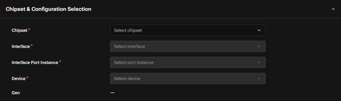
- Chipset (required): Select the applicable chipset from the dropdown.
- Interface (required): Select the high-speed interface to analyze (e.g., PCIe, USB, QLINK). Available options depend on the selected chipset.
- Interface Port Instance (required): Select the specific port instance for the interface.
- Device (required): Select the device connected to the processor through the selected interface.
- Gen: Automatically displayed based on your device selection.
NOTE
Simulation validation runs automatically when all configuration fields are selected. A progress overlay will appear during validation.
Upload Layout File
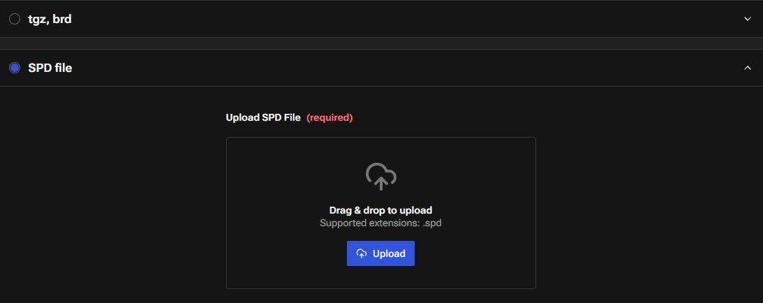
Upload the PCB layout file (required). Supported formats:
- ODB++ (.tgz): Tool-independent format
- Cadence Board (.brd): Allegro board file
- Cadence SPD (.spd): Extracted design file
If you upload an ODB++ or .brd file, click the Translate button to convert it to SPD format.
Step 2: Project & Board Information
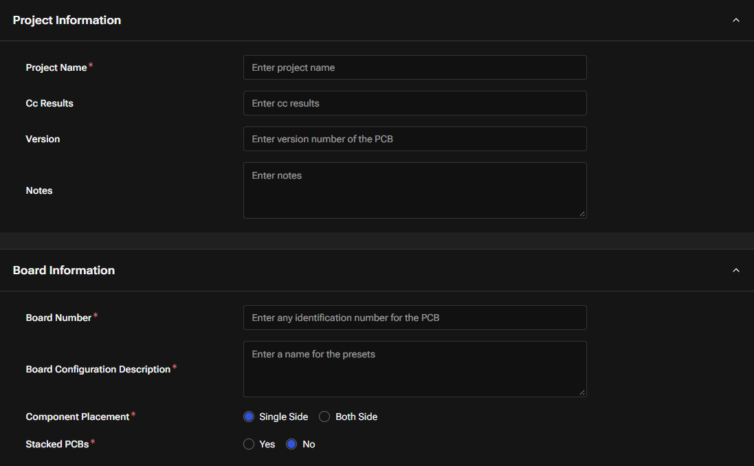
- Project Name (required): Enter the name of your project.
- Cc Results: Enter email addresses to receive job completion notifications. Multiple addresses can be separated by commas.
- Version: Enter version number of the PCB (Optional). This is for your tracking purpose.
- Notes: Add any notes about the design or configuration.
- Board Number (required): Enter any identification number for the PCB. This is for your tracking purpose.
- Board Configuration Description (required): Enter a name for the presets.
- Component Placement (required): Select Single Side or Both Side.
- Stacked PCBs (required): Select Yes or No.
Step 3: Processor & Device
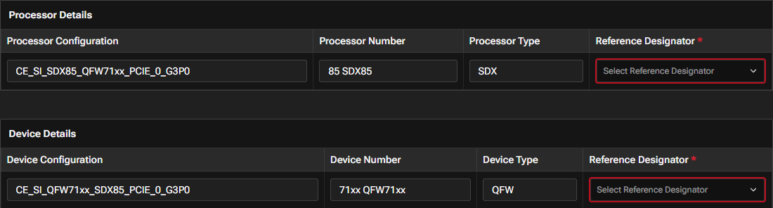
The Processor Details and Device Details tables are prefilled based on your chipset, interface, port instance, and device selections from Step 1.
For each table, select the Reference Designator (Ref Des) (required) from the dropdown. These options are extracted from the uploaded PCB file (SPD/brd/tgz).
Step 4: SI Group
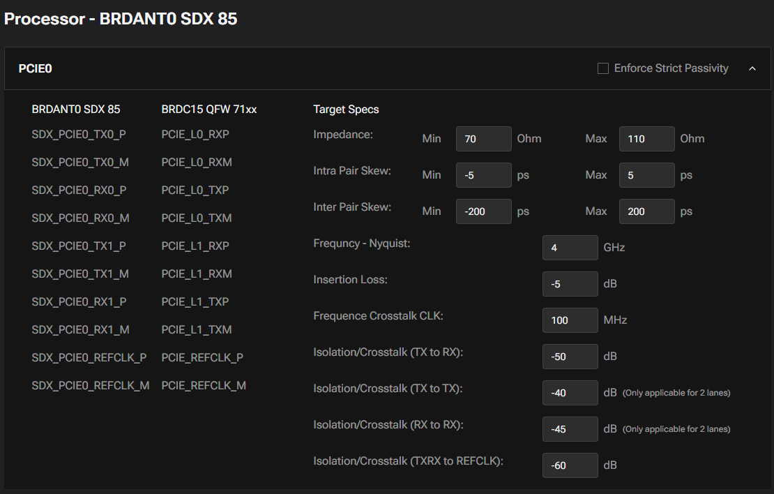
- SI Group configurations are automatically generated based on your processor and device selections from Step 3. Each configuration displays the processor and device ports included in the analysis.
- Target specifications (impedance, skew, insertion loss, crosstalk isolation, etc.) are automatically loaded based on the selected interface and generation.
- Enable Enforce Strict Passivity to apply stricter passivity constraints during simulation.
Step 5: Stackup Information

- To override stackup values, download the template, update it, and upload the modified file.
- Select the Unit for layer thickness (um or mm).
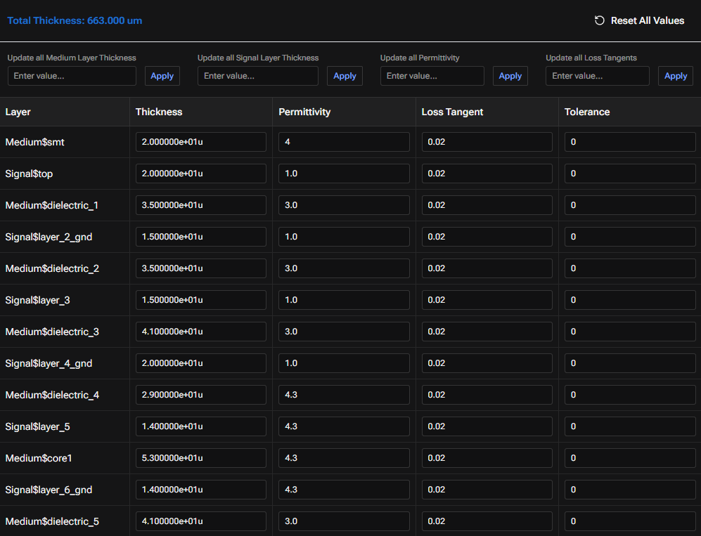
- The table displays Layer, Thickness, Permittivity, Loss Tangent, and Tolerance. You can edit values directly in the table or use the bulk update options to apply the same value across all Medium Layer Thickness, Signal Layer Thickness, Permittivity, or Loss Tangent fields.
- Click Reset All Values to reload the original values from the uploaded PCB.
Step 6: Select Component Models
NOTE
Component Type selection guidance:
- For AC Coupling Capacitors, select Component Type → DC-Blocking.
- For Series Resistors, select Component Type → Resistor.
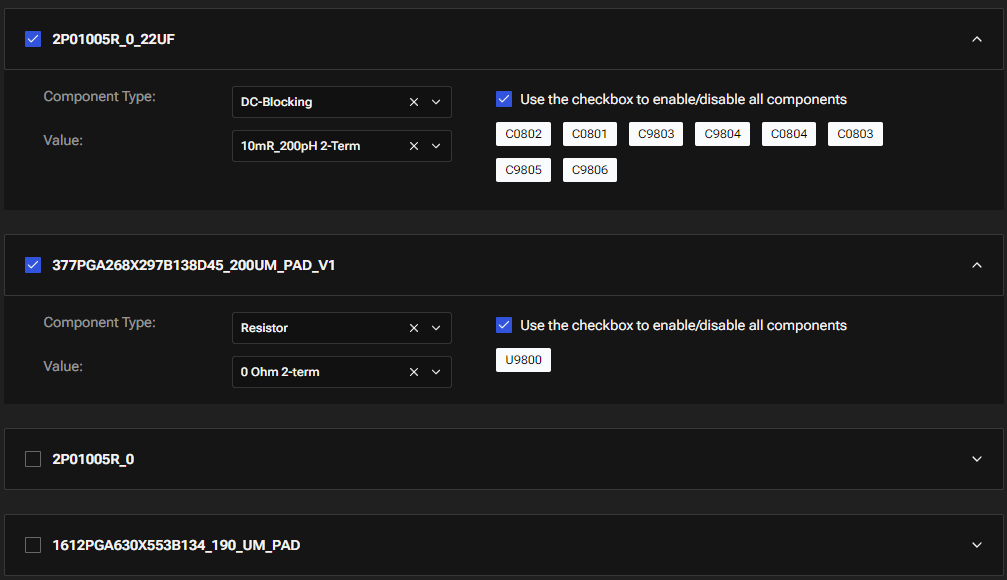
- Component models are shown as collapsible panels. Click the checkbox to expand and configure each component model.
- For each selected component model, select the Component Type and Value from the dropdowns.
- Click individual component tags to enable or disable them, or use the checkbox to enable/disable all components at once.
Preview & Submit
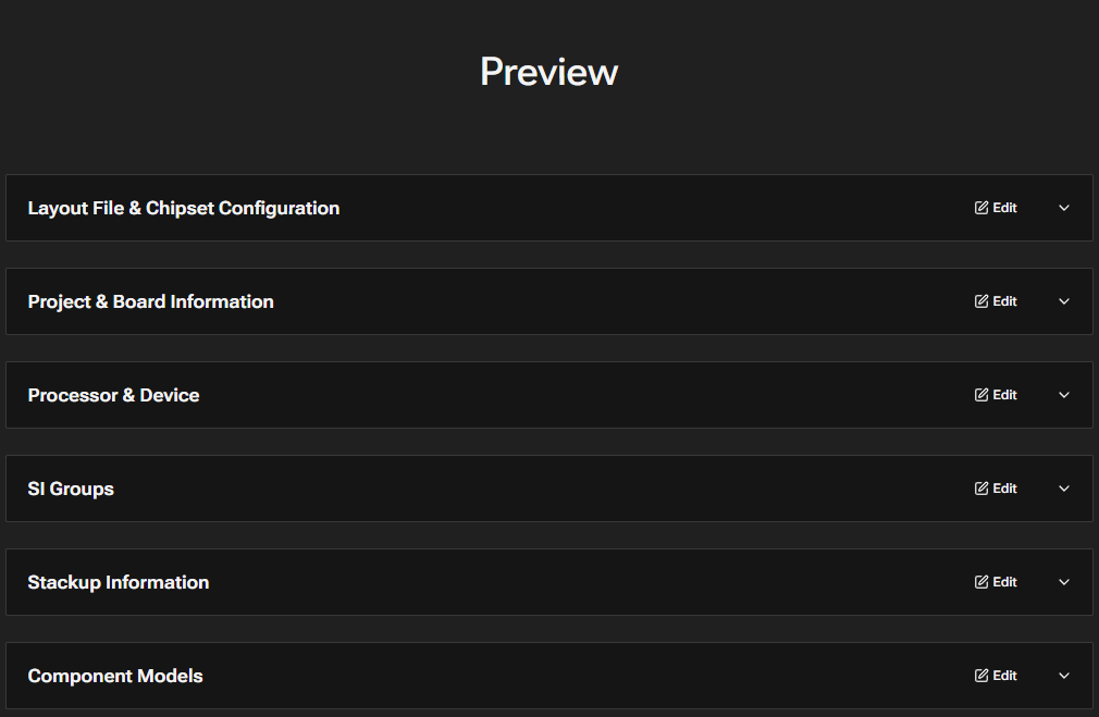
The Preview page displays a read-only summary of all configured settings. Each panel has an Edit button to navigate back to that step if changes are needed.
Click Submit Job to start the simulation. After successful submission, you will receive a Job ID and can track the job status on the Job History page.